个人简介
enjoy code,enjoy life!
文章分类
全部博文(22)
- gsm/gprs模块开发(1)
- c#(7)
- linux设备驱动开(2)
- c/c 学习笔记(7)
- pic32(3)
- altium designer(1)
- μc/os-ii(1)
- 数据结构(0)
- 未分配的博文(0)
相关博文
- ·
- ·
- ·
- ·
- ·
- ·
- ·
- ·
- ·
- ·
分类: 嵌入式
2012-07-25 08:47:16
mcu到keyboard的通讯协议
注:mcu到keyboard的通讯主要用在控制键盘上的led灯(numlock,capslock和scrolllock)
1.首先介绍下ps/2接口和发送的帧位:
如图1和图2所示,ps/2的接口定义如下:
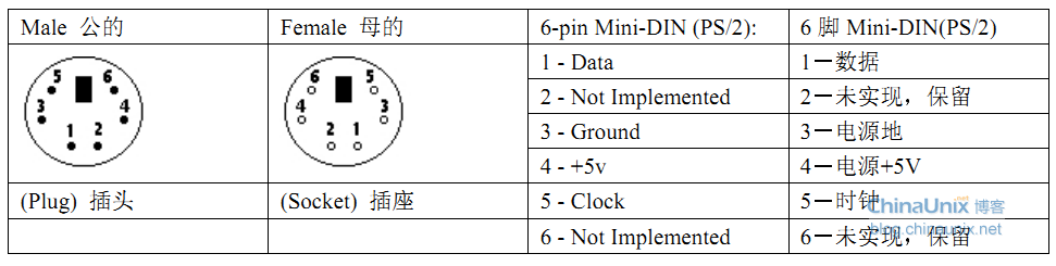
图1.ps/2接口定义
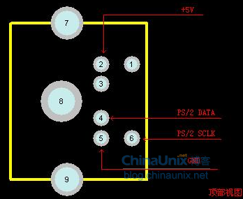
图2.ps/2接口母座定义
图3为ps/2串行通讯协议中每帧11位数据的定义,如下图所示:
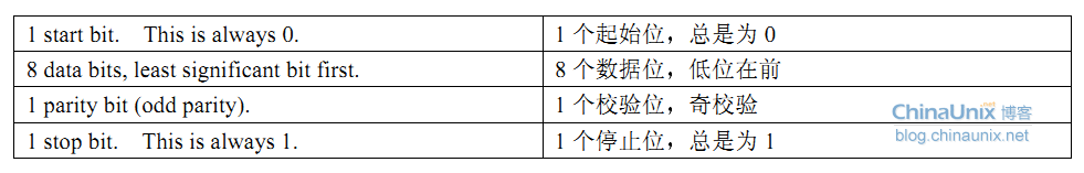
图3.ps/2每帧11位的串行协议
2.ps/2协议的详细通讯过程
ps/2设备总是产生时钟信号.如果主机要发送数据,它必须首先把时钟和数据线设置为"请求发送"状态.可以通过下拉时钟线至少100微秒来抑制通讯,通过下拉数据线来应用"请求发送",然后释放时钟.设备应该在不超过10毫秒的间隔内就要检查这个状态.当设备检测到这个状态,它将开始产生时钟信号,并且时钟脉冲标记下输入八个数据位和一个停止位.主机仅当时钟线为低的时候改变数据线,而数据在时钟脉冲的上升沿被锁存.这在发生在设备到主机的通讯的过程中正好相反.在停止位发送后不释放数据线,设备将继续产生时钟脉冲直到数据线被释放(然后设备将产生一个错误).
要使得这个过程易于理解,主机必须按下面的步骤发送数据到ps/2设备:
1.把时钟线拉低至少100微秒.
2.把数据线拉低.
3.释放数据线.
4.等待设备把时钟线拉低.
5.设置/复位数据线发送第一个数据位.
6.等待设备把时钟线拉高.
7.等待设备把时钟线拉低.
8.重复5~7步骤,发送剩下的7个数据位和校验位.
9.释放数据线.
10.等待设备把数据线拉低.
11.等待设备把时钟线拉低.
12.等待设备释放数据线和时钟线.
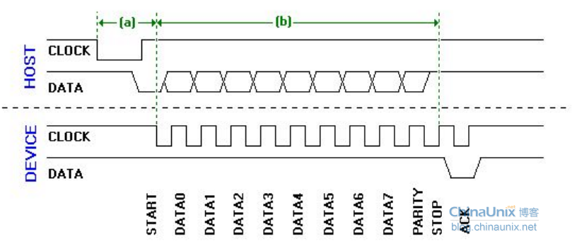
图4.主机到设备的详细通讯过程
3.如下是debug版的host to device的ps/2通讯代码:
其中有很多处return,主要是用于观测返回值,看看通讯出错的地方.另外timer_10ms[4]是一个定时器,防止程序死机用的.如果调试成功也可以把这些都去掉.
点击(此处)折叠或打开
- #define ps2kb_sendbyte_success 0
- byte _ps2kb_sendbyte(byte idata)
- {
- byte i;
- byte temp;
- byte tempc;
- bool flag_check = 1;
- temp = idata;
- for(i = 0; i < 8; i)
- {
- tempc = temp & 0x01;
- if(tempc == 0x01)
- flag_check = !flag_check;
- temp = temp >> 1;
- }
- pd_ps2_clk_tris = 0;
- pd_ps2_clk_lat = 0;
- delay_us(100); //bring the clock line low for at least 100 microseconds
- pd_ps2_data_tris = 0;
- pd_ps2_data_lat = 0;//bring the data line low
-
- delay_us(20);
- pd_ps2_clk_tris = 1; //release the clock line.
-
- temp = idata;
- for(i = 0; i < 8; i)
- {
- tempc = temp & 0x01;
- while( timer_10ms[4]&& pd_ps2_clk_io ); //wait for the device to bring the clock line low
- if( ! timer_10ms[4] ) return (ii1);
-
- if(tempc == 0x01) //set/reset the data line to send the data bit
- pd_ps2_data_lat = 1;
- else
- pd_ps2_data_lat = 0;
- temp = temp >> 1;
- while( timer_10ms[4]&& !pd_ps2_clk_io ); //wait for the device to bring clock high.
- if( ! timer_10ms[4] ) return (ii2);
-
- }
- while( timer_10ms[4]&& pd_ps2_clk_io ); //wait for the device to bring the clock line low
- if( ! timer_10ms[4] ) return 17;
- if(flag_check == 0x01) //set/reset the data line to send the parity bit
- pd_ps2_data_lat = 1;
- else
- pd_ps2_data_lat = 0;
-
- while( timer_10ms[4]&& !pd_ps2_clk_io ); //wait for the device to bring the clock line high.
- if( ! timer_10ms[4] ) return 18;
- while( timer_10ms[4]&& pd_ps2_clk_io ); //wait for the device to bring the clock line low
- if( ! timer_10ms[4] ) return 19;
-
- pd_ps2_data_tris = 1; //release the data line
- while( timer_10ms[4]&& pd_ps2_data_io ); //wait for the device to bring data low
- if( ! timer_10ms[4] ) return 20;
- while( timer_10ms[4]&& pd_ps2_clk_io ); //wait for the device to bring clock low
- if( ! timer_10ms[4] ) return 21;
-
- while( timer_10ms[4]&& (!pd_ps2_data_io || !pd_ps2_clk_io) ); //wait for the device to release data and clock
- if( ! timer_10ms[4] ) return 22;
-
- // the following is to receive the ack data
-
- while( timer_10ms[4]&& pd_ps2_clk_io ); //wait for the device to bring the clock line low
- if( ! timer_10ms[4] ) return (23);
-
- if(pd_ps2_data_io) return (24);//read the data line to check the start bit
-
- while( timer_10ms[4]&& !pd_ps2_clk_io ); //wait for the device to bring clock high.
- if( ! timer_10ms[4] ) return (25);
-
- flag_check = 1;
- for(i = 0; i < 8; i)
- {
- while( timer_10ms[4]&& pd_ps2_clk_io ); //wait for the device to bring the clock line low
- if( ! timer_10ms[4] ) return (ii26);
-
- if(pd_ps2_data_io) flag_check = !flag_check;
-
- temp |= ((((byte)pd_ps2_data_io) & 0x01) << i);
-
- while( timer_10ms[4]&& !pd_ps2_clk_io ); //wait for the device to bring clock high.
- if( ! timer_10ms[4] ) return (ii27);
-
- }
-
- if( temp != ps2_keycmd_ack )
- {
- return 42;
- }
-
- while( timer_10ms[4]&& pd_ps2_clk_io ); //wait for the device to bring the clock line low
- if( ! timer_10ms[4] ) return 43;
- if( flag_check) return 44; //read the data line to check the parity bit
-
- while( timer_10ms[4]&& !pd_ps2_clk_io ); //wait for the device to bring clock high.
- if( ! timer_10ms[4] ) return 45;
-
- while( timer_10ms[4]&& pd_ps2_clk_io ); //wait for the device to bring the clock line low
- if( ! timer_10ms[4] ) return 46;
- if(!pd_ps2_data_io) return 47; //read the data line to check the stop bit
-
- while( timer_10ms[4]&& !pd_ps2_clk_io ); //wait for the device to bring clock high.
- if( ! timer_10ms[4] ) return 48;
- return ps2kb_sendbyte_success;
- }
键盘led灯无法点亮问题
尽管有了上面的程序但是我之前也未能实现键盘上led灯的点亮(有些键盘可以,但有些键盘不行),这个问题困扰了我很久,偶然的机会配到一个资深的工程师帮我解决了这个问题,问题如下:
图1为dr100上ps/2接口部分的电路.因为dr100用的是ttl的电平,所以dr100管脚输出的高电平为3.3v.即ps/2 data端和ps/2 clk端的电平都为3.3v.而ps/2 vcc(即c点电位)为5v.通过计算可得a点与b点的电位约为3.41v.但是由于小键盘采用的是cmos电平,而cmos的高电平是定义为大于3.5v的电平,所以无法驱动小键盘.
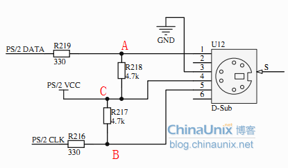
图5.ps/2接口电路
待我把r216和r219的电阻短路后后便可以点亮led灯了.
给主人留下些什么吧!~~